K3NG Arduino Rotator Controller
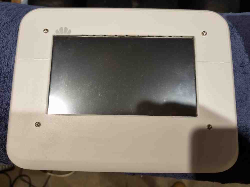 Photo 1
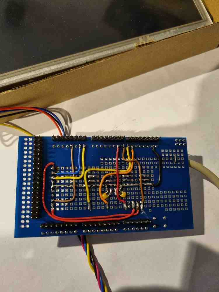 Photo 2
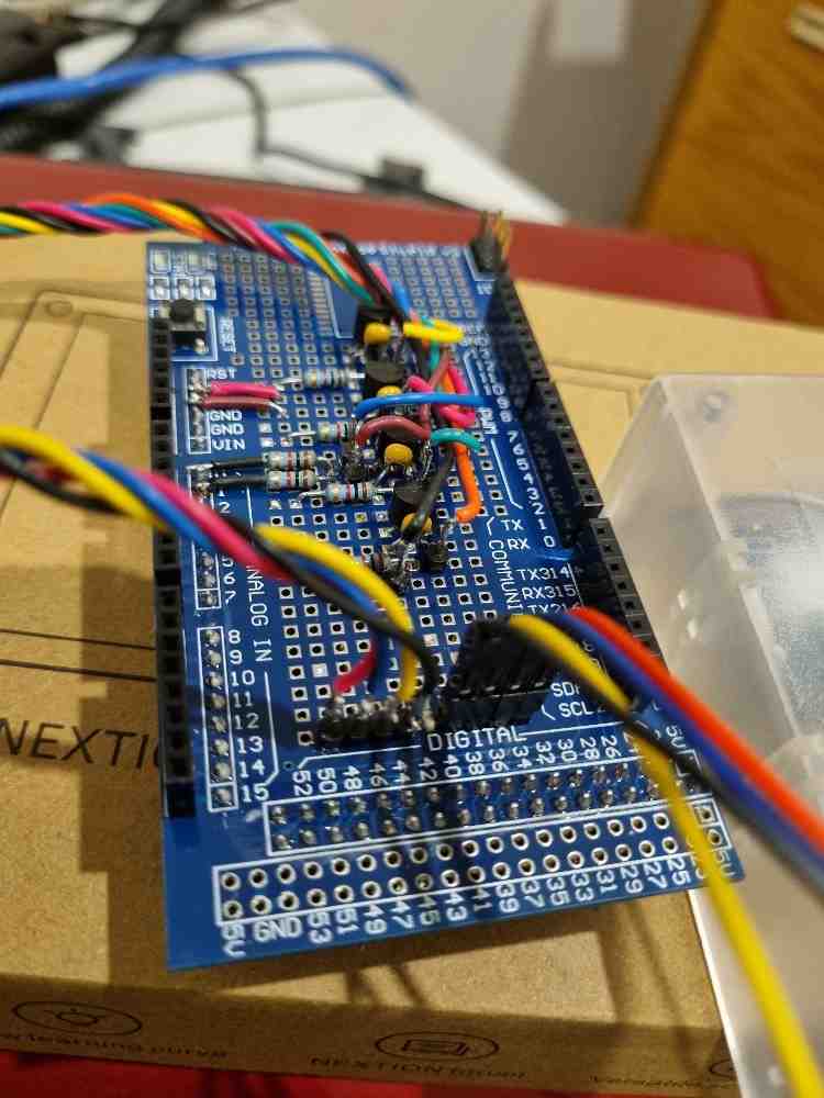 Photo 3
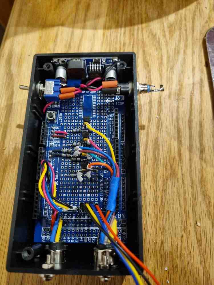 Photo 4
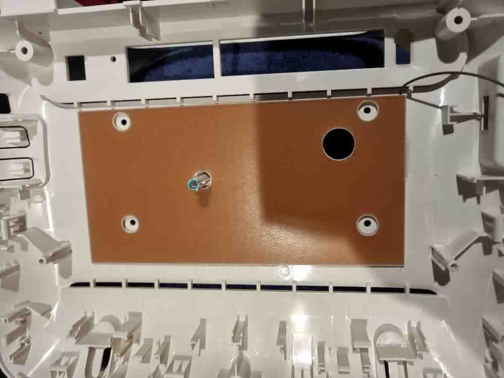 Photo 5
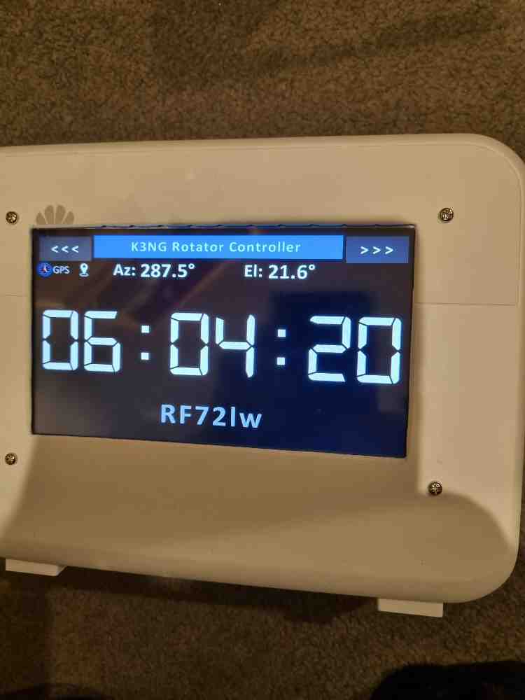 Photo 6
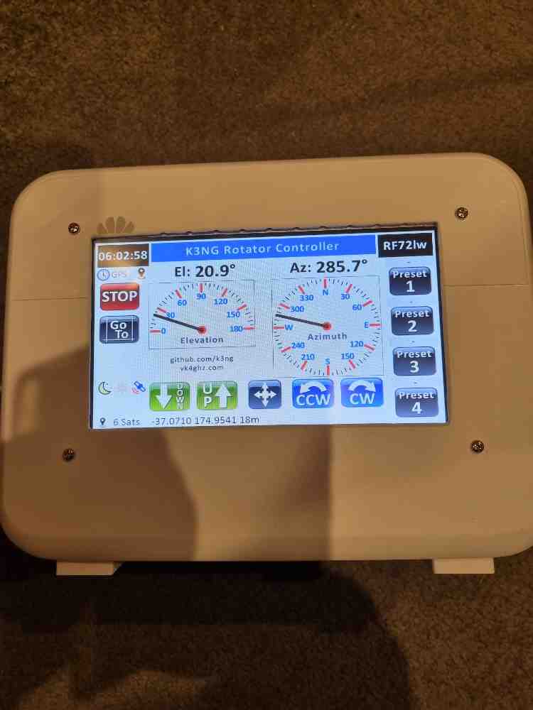 Photo 7
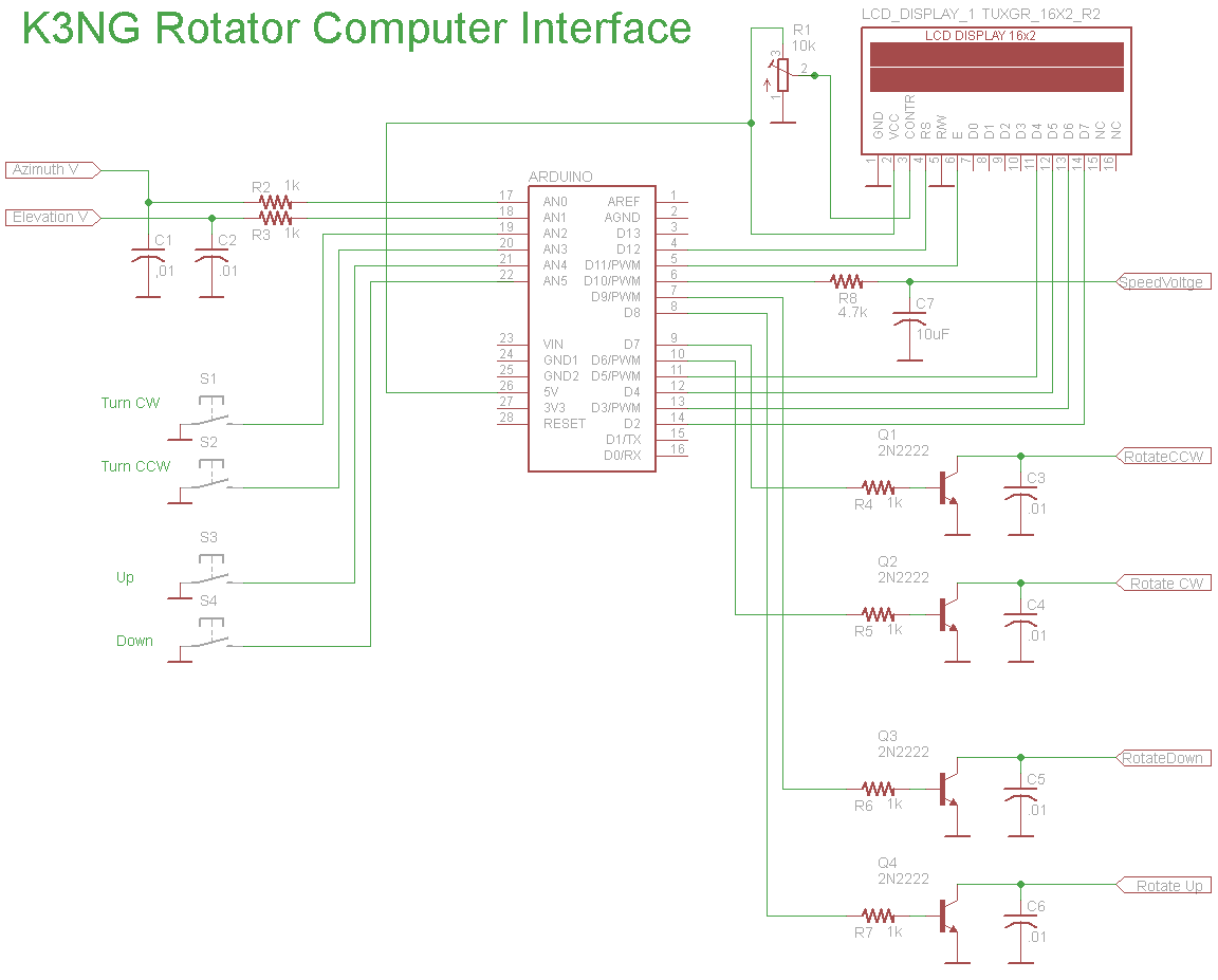 Photo 8
Back to Top
Photo 1
Photo 2
Photo 3
Photo 4
Photo 5
Photo 6
Photo 7
Photo 8
Back to Top
Photo 8
Back to Top
Photo 1
Photo 2
Photo 3
Photo 4
Photo 5
Photo 6
Photo 7
Photo 8
Back to Top
K3NG ARDUINO ROTATOR PROJECT
This is an Arduino-based rotator interface that interfaces a computer to a rotator or rotator controller, emulating the Yaesu GS-232A/B, Easycom, and DCU-1 protocols which are supported in a great number of logging, contest, and control programs. It can be easily interfaced with commercial rotator control units. This unit could also serve as a total replacement for a rotator control unit or serve as the basis for a 100% homebrew rotation system. Several azimuth and elevation position sensors including potentiometers, rotary encoders, and I2C devices are supported. The code is very flexible, modular, and easy to read allowing you to customize it to suit your needs.
Photo 1. Shows the 7" Nextion Display, which has been put into an old router case. You can use any case for this project but I came up with this idea and used this old router case for this project, and especially as I had it lying around. I removed everything inside leaving just the case shell. I cut out using a paper template and marked out where the 7" Nextion display will be mounted. Adam VK4GHZ came up with the 7.0″ Nextion version firmware for the K3NG Rotator Controller. The arduino mega and prototype board did not fit inside the case so I fitted and added another plastic box that fitted the arduino perfectly and mounted to the back of the case. I did not use the lid of this case and made another paper template and drilled 4 holes to mount the arduino case, screwed from the inside.
Photo 2. After getting this all working I made all wires as short as possible. This is the end result of the under side of the Arduino project board.
Photo 3. This is the top side of the Arduino project board doing the same to make all wires as short as possible.
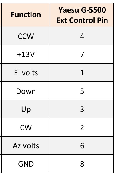
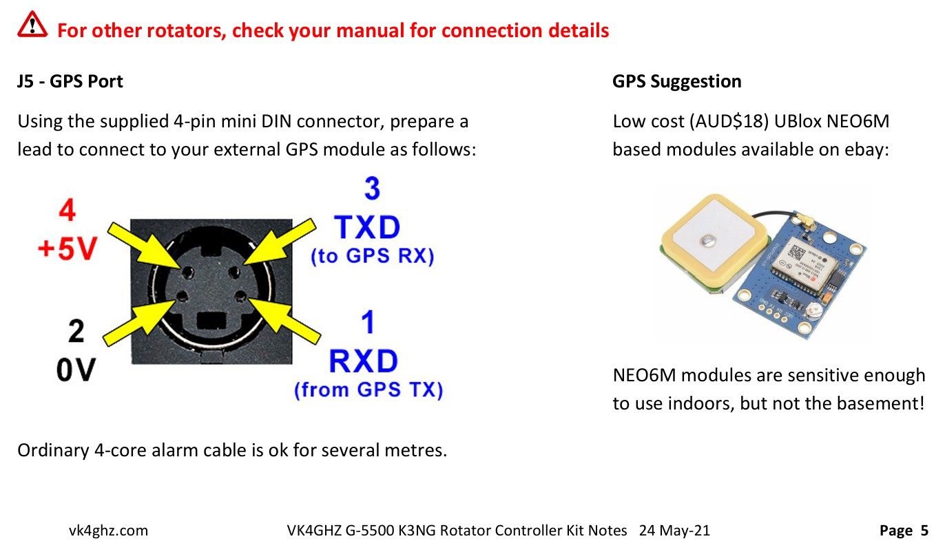
Photo 4. The finished version. Everything is mounted in the plastic project box, ready to be screwed to the back of the router case. The Arduino Mega is underneath the proto-type board and you can also see one of the buck converters which fitted snugly down the side. The other buck converter is a smaller version. One to power up the display and the other for the arduino 8v. using a 12v input. I fitted two sockets, a mini din socket (PS2) and 8 pin din. The mini din (PS2) socket is for the GPS module and the 8 pin din socket is to connect to the Yaesu G-5600B Rotator. Both leads are wired up each end with the same pin configuration. I added an on/off switch to switch the 12v input.
Photo 5. This is the inside back cover of the router. The brown board is a copper clad board on the other side. This was used to screen the arduino and the display. I drilled 4x holes to mount the arduino on the back of the router case making a hole for the display cable. At the top RHS you will see a wire which is attached to the copper clad board to be connected to ground or earth.
Photo 6. This photo shows the GPS clock working on the display and the case is not yet sprayed and sign written which I still plan on doing.
Photo 7. This photo shows the K3NG rotator controler all working and operates by touch commands or of course automatically by computer program through your radio's interface.
Photo 8. This is the schematic diagram. For more information for this
project, it can be found here on this link.
K3NG Arduino Rotator Controller wiki Link
 GPS Pinouts
Check out Adam's Series of YouTube Video's Click on the links below.
VK4GHZ Nextion for K3NG Rotator
controller Part 1 - Basic Az system
To get the software click here K3NG Rotator Controller software Link click on the green button marked "<> Code" and click on downlaod zip. Have fun
For more info on the firmware and programming the 7" display and for smaller nextion displays firmware check out Adam's website. Click here VK4GHZ K3NG Rotator controller firmware Link
I would also like to thank Ian ZL1AOX who inspired me to make this project and also with all his help with programming and with the great advice throughout this project. Thanks Ian
© 2024 ~ ZL1RJS